—simplified hydraulic circuit schematic for the motor efficiency test Motor control circuits Wire motor control diagram circuit ladder basics
MOTOR CIRCUITS AND CONTROL – Applied Industrial Electricity
Ladder diagram basics #3 (2 wire & 3 wire motor control circuit) Motor circuits and control – applied industrial electricity Motor ladder logic control circuit plc circuits diagram electric programming relay wiring diagrams electrical controls system simulation starter shutdown example
Circuit motor simplified piston efficiency diagram valve directional
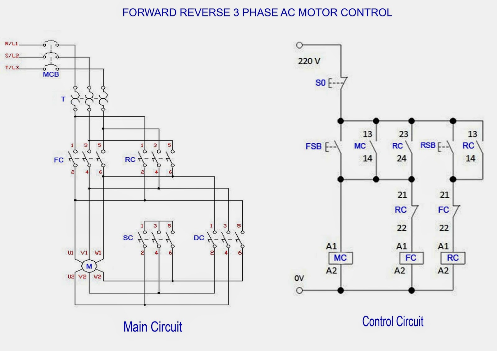
Reverse wiring rangkaian diagrams windingWiring motors arranque paro controlling circuito giro trifasico hilos Forward reverse 3 phase ac motor control wiring diagramWiring diagram ng motor.
11+ three phase motor control circuit diagram .


Forward Reverse 3 Phase AC Motor Control Wiring Diagram | Electrical

MOTOR CIRCUITS AND CONTROL – Applied Industrial Electricity
—Simplified hydraulic circuit schematic for the motor efficiency test

Motor Control Circuits | Ladder Logic | Electronics Textbook

Wiring Diagram Ng Motor - Home Wiring Diagram

11+ Three Phase Motor Control Circuit Diagram | Robhosking Diagram